
How to Install the AR-15 Lower Parts Kit
Posted by 80-Lower.com on Aug 24th 2022
Installing the lower parts kit in your AR-15's lower receiver should take less than two hours for first-time builders. This guide will illustrate how to perform each assembly and install step with pictures and written instructions.
We strongly recommend finding the right tools before you get started, lest you end up with missing roll pins and springs that flew off into the carpet, never to be found again (you don't want to put a pause on your install half-way through). This guide is applicable for both a finished 80% lower and a "retail" stripped lower receiver.
Tools Required
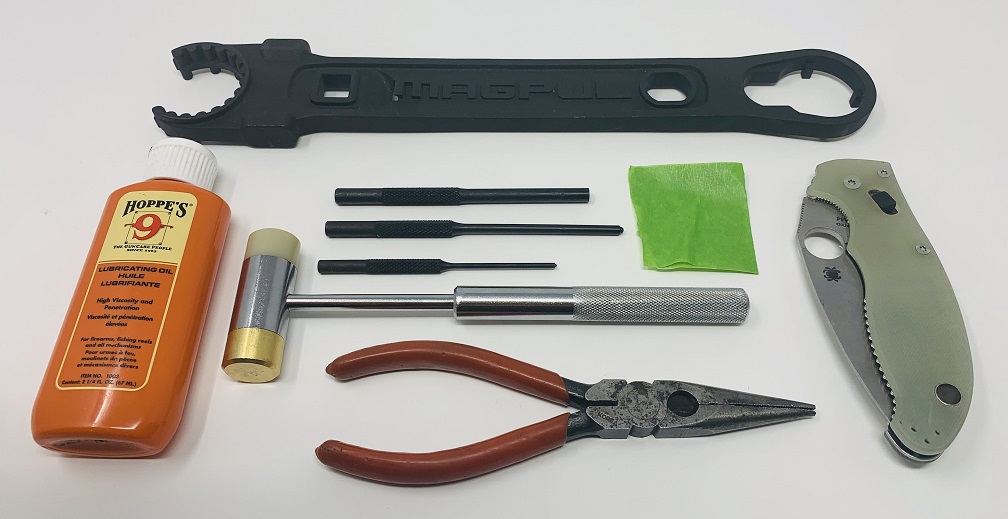
- Roll Pin Punches. You'll want three punches: 3/32", 1/8", and 5/32". The last two are optional but helpful, while the first is essential: You'll need the 3/32" punch to install the roll pins for the bolt catch and trigger guard.
- Gunsmithing Hammer. To be used with your punches, the hammer will also help with installing the pins for the hammer and trigger, which make for a tight fit.
- Needle-Nose Pliers. Useful for handling the tiny detents and springs that retain the takedown and pivot pins.
- Masking Tape. Useful for covering up your receiver's finish to prevent damage while hammering and using the punches. This is of particular concern when installing the bolt catch roll pin.
- Razor or Knife. Useful for keeping the spring-loaded detent compressed when installing the front takedown pin.
- Lubricant. Essential for making pins slide in easily, lubricant will also help protect your anodized finish.
- 3/16" Allen Key. Required to install the pistol grip's screw and washer.
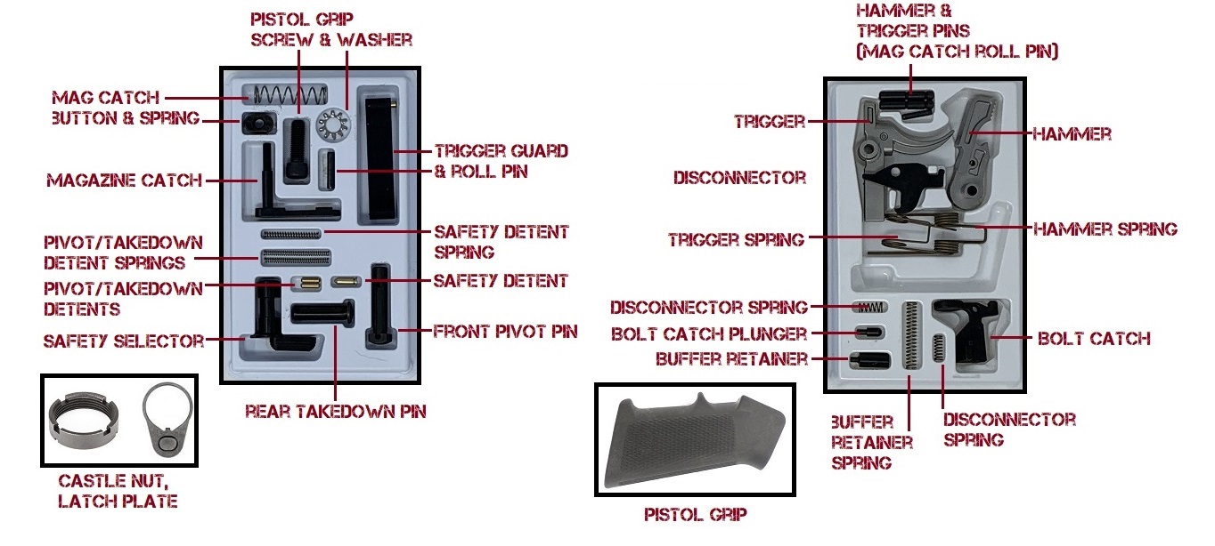
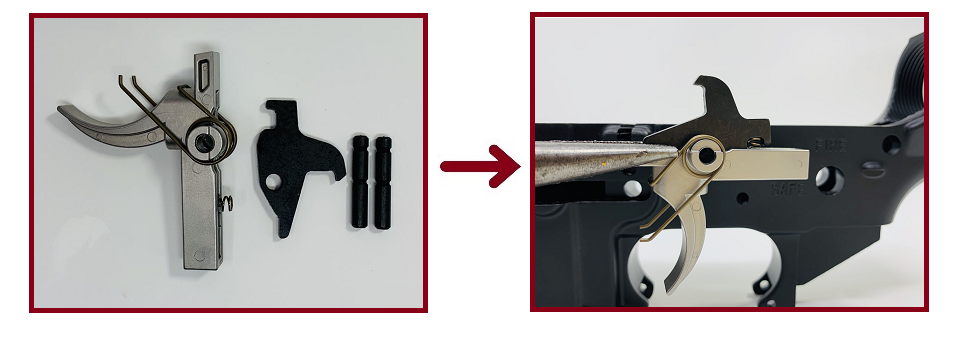
Lower Parts Kit Diagram
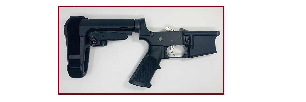
Before starting the assembly, verify you have all the required parts. For our install, we're using the Anderson Stainless AR-15 LPK. This is considered a "mil-spec" parts kit, it runs very smoothly, and it's affordable. A mil-spec LPK includes a single-stage trigger and factory springs, pins, detents, and parts. We're installing a pistol brace instead of a buttstock, but we're still using a standard carbine buffer tube and castle nut. Mechanically, this is no different than any other mil-spec kit install for an AR pistol or rifle chambered in 5.56/.223 (or 300 Blackout).
1. Assemble the Trigger and Trigger Spring
- Parts: Trigger, Trigger Spring.
- Tools: None
Orient the trigger and spring as shown. Slide one loop of the spring over the trigger pin hole housing, then repeat on the opposite side. Ensure the metal wire connecting both loops rests underneath the sear (the front, flat part of the trigger) as shown.
2. Install the Disconnector Spring
- Parts: Disconnector Spring, Trigger.
- Tools: 3/32" Punch (optional)
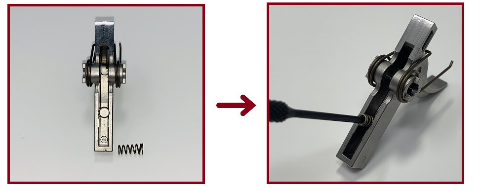
Orient the trigger vertically, and collect the disconnector spring from the kit. The spring is easily identified because it's the only spring that is fatter on one end. Insert the fat end of the spring into the recessed hole atop the trigger as shown. It's a tight fit, so applying some lubricant is helpful. Ensure the bottom of the spring is fully seated. You can use the 3/32" punch to gently push the spring down until it is fully seated.
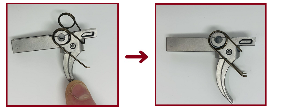
3. Assemble the Hammer and Hammer Spring
- Parts: Hammer, Hammer Spring.
- Tools: None
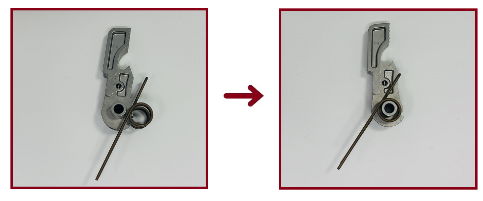
In the same fashion as the trigger, install the hammer spring onto the hammer. Ensure the metal wire connecting both loops rests behind the hammer hook, shown above.
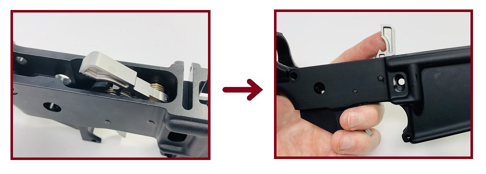
4. Install the Trigger and Disconnector
- Parts: Receiver, Trigger, Disconnector, Trigger Pin.
- Tools: Lubricant, Gunsmithing Hammer.
First, grab the disconnector and one of the two trigger/hammer pins. It doesn't matter which pin you grab; they are the same. Orient the trigger as shown and place the disconnector atop the trigger so the holes in both units line up. The notch in the disconnector should rest directly atop the disconnector spring in the trigger.
Drop the trigger and disconnector into the lower receiver. With gentle pressure applied to the trigger and disconnector, the holes in both units and the pin hole in the receiver should align. Lubricate the trigger pin hole, and insert the trigger pin while maintaining pressure on the assembly. The pin should be inserted from the left side of the receiver with the grooves in the pin going in first. Use the gunsmithing hammer to gently tap the trigger pin in place.
NOTE: If you meet resistance, flip the receiver over and check the opposite pin hole to verify the holes in the disconnector, trigger, and receiver are all aligned while pushing the pin in. Do not try to force the pin through.
Continue tapping the trigger pin until it's flush with both sides of the receiver. Wipe away excess oil, then double-check the trigger inside the fire control cavity. Ensure the ends of the trigger spring rest on the floor of the cavity, and that both trigger spring loops are still seated on the round shoulders of the trigger itself.
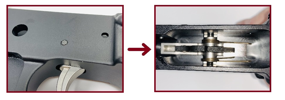
5. Install the Hammer and Hammer Pin
- Parts: Hammer, Hammer Pin.
- Tools: Lubricant, Gunsmithing Hammer.
Orient the hammer as shown above and drop it into the fire control cavity. The ends of the hammer spring should rest atop the trigger pin, in the notches on either side of the trigger's round shoulders. Like we did with the trigger, we need to apply pressure to the hammer and its spring to align the pin holes. The hammer spring is much stiffer than the trigger spring; it will require some additional force to maintain alignment.
NOTE: To assist with the pin insertion, lubricate both the receiver and hammer pin hole. If the pin is a tight fit, gently tap it into the receiver partially before inserting the hammer, then apply pressure to the hammer and continue seating the pin. The pin should be flush on both sides of the receiver.
Once installed, check the function of the hammer and trigger: Cock the hammer as shown left to confirm the sear on the trigger catches and holds the hammer down. With a finger on the trigger and hammer face, pull the trigger. The hammer should release. Don't let the hammer release at full force or it could crack the receiver's magazine well. Once released, continue holding the trigger down. Press the hammer back down and confirm it catches the hook on the disconnector. Once it does, take your finger off the trigger. The disconnector hook should slide off the hammer hook, allowing the sear to catch the hammer once again, keeping it cocked. You should hear a slight "pop".
If your hammer/trigger does not function, see bottom of guide for troubleshooting trigger reset failure.
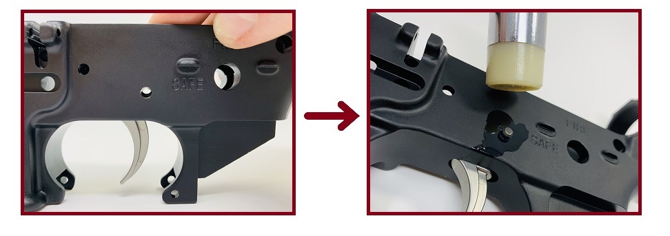
6. Install the Trigger Guard
- Parts: Trigger Guard, Trigger Guard Roll Pin.
- Tools: 3/32” Punch, Lubricant, Gunsmithing Hammer, Pliers (or Wood Shim).
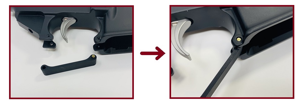
Next up is the trigger guard. This install involves our first roll pin (the longer of the two provided in the kit), so grab your 3/32" punch. First, press down on the pre-installed spring-loaded pivot pin and insert that end of the guard into the front ears of the trigger well. Next, align trigger guard's rear pin hole with the two holes in the ears at the rear of the trigger well.
The roll pin is a very tight fit. It helps to lubricate both ear holes, the trigger guard hole, and the pin. Tap the pin into place with the 3/32" punch and hammer. There is a risk of bending and breaking the ears if they are not supported underneath. The rubber handle on your pliers works well for deadening your hammer blows, but a small wood shim works, too. Tap the pin into place until it's flush with both holes on the ears of the trigger well. If you meet excess resistance, do not try to force the pin in place. Ensure the guard's still aligned while hammering.
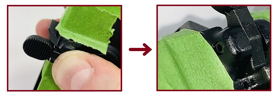
7. Install the Magazine Catch & Magazine Release
- Parts: Magazine Catch, Mag Catch Spring, Magazine Release Button.
- Tools: Lubricant, 5/32" Punch or Pencil (Optional).
Install the magazine catch by inserting the threaded portion through the magazine well's recessed channel and hole in the left side of the receiver. Flip the receiver over to install the spring and magazine release button.
TIP: To keep the catch seated, place the handle from your punch underneath the receiver to support it. A wood pencil works, too.
Next, install the magazine catch spring. It's the widest spring with the fewest coils in the kit. Then thread the magazine release button onto the magazine catch threads. Thread the button on until it's nearly flush with the hole in the receiver.
NOTE: Threading the button onto the catch requires compressing the spring underneath, which tends to fight the button. Be careful not to cross-thread the button, or the catch may be ruined. It helps to apply some lubricant to the button and threads.
With the button partially threaded, flip the receiver over. You'll need to press the button into the receiver as far as possible to thread the magazine catch and button together fully. It helps to press the button in with the 5/32" punch. Rotate the catch approximately 3 to 4 turns, align it with the channel, and release the button. The backside of the magazine release button should be seated just below the rim of the hole, nearly flush but recessed. Insert an empty magazine and test the catch and release button to confirm its function.
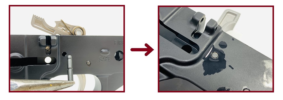
8. Install the Bolt Catch
- Parts: Bolt Catch Lever, Bolt Catch Roll Pin, BC Plunger, BC Plunger Spring.
- Tools: Lubricant, Masking Tape, 3/32" Punch, Gunsmithing Hammer (and some patience).
Collect the bolt catch, plunger, spring, and roll pin. This step requires the use of the 3/32" punch and gunsmithing hammer, and the risk of damaging the anodized finish on the receiver is high. To prevent scratching, use some masking tape to cover up the receiver around the bolt catch mount and roll pin holes. Then insert the spring.
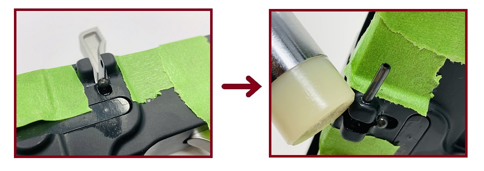
Next, insert the plunger atop the spring. We're again applying pressure to align the holes for the pin like we did for the trigger and hammer, so lubricating the bolt catch, spring, and roll pin holes are encouraged. Unless you have a buddy helping (or you have three hands), getting the roll pin started while keeping the catch aligned is difficult. It helps to get the pin partially seated inside the bolt catch roll pin hole by gently tapping it in with your hammer.
NOTE: Do not hammer the pin all the way through the first side, or it won't allow you to insert the bolt catch. Once the pin is partially seated, insert the bolt catch so it's resting atop the plunger.
Apply gentle pressure to align the holes. Continue tapping the roll pin into place until it is fully seated on both sides of the bolt catch housing. Again, do not try to force the pin through. If you meet excess resistance, check alignment by viewing through the opposite hole. The pin should be just slightly recessed inside each hole once installed.
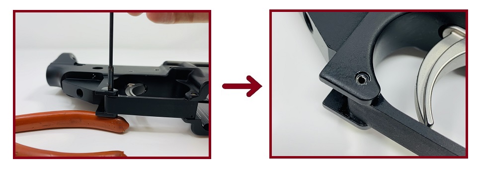
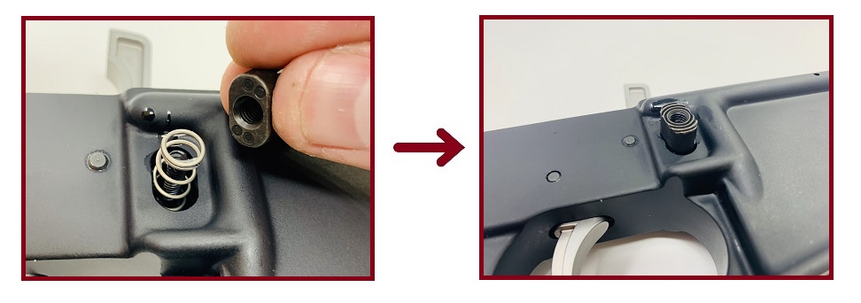
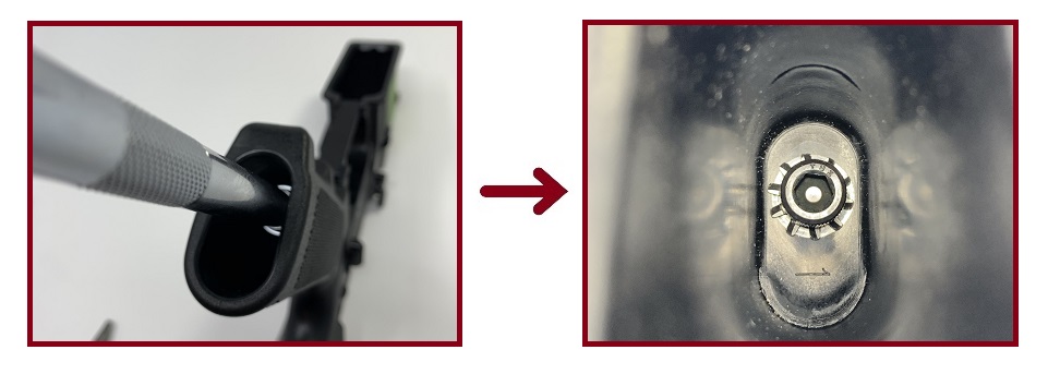
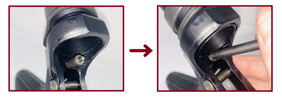
9. Install the Front Pivot Pin
- Parts: Front Pivot Pin, Pivot Pin Detent, Detent Spring.
- Tools: Lubricant, Needle-Nose Pliers, Razor Blade or Knife Edge.
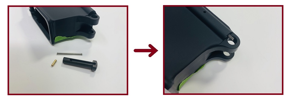
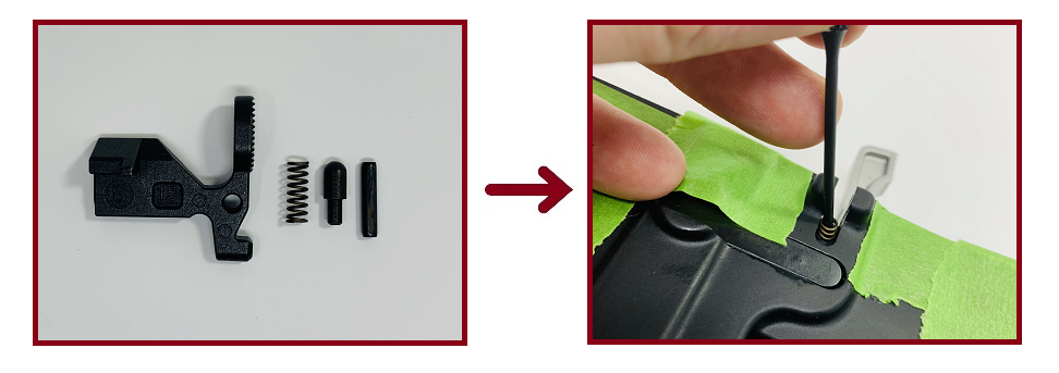
Collect the front pivot pin, pivot detent and spring from the kit. Insert the spring into the pivot pin detent hole.
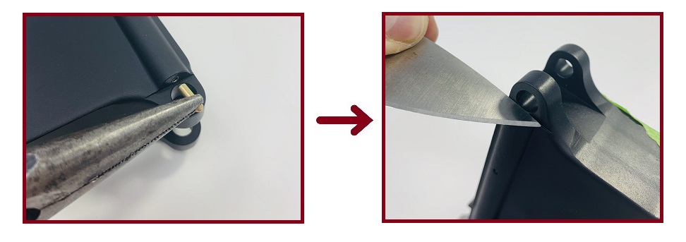
Next, use pliers to insert the pivot pin detent atop the spring and compress it down into the hole. The spring will provide plenty of tension on the detent. Be very careful! The detent will fly out of the hole if you let it slip. It will launch across the room and into the abyss, halting your install. Take your time compressing it. Use a dull razor blade or knife to keep the spring compressed while inserting the pivot pin.
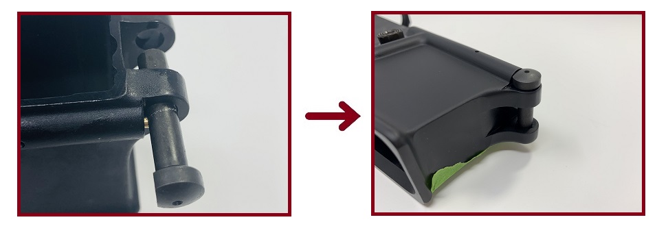
While keeping the spring and detent compressed, insert the pivot pin into its mounting hole. The thin blade or knife should provide just enough room for this to occur. Lubrication is helpful, as the anodized finish will initially make for a tight fit. Once inserted, remove the knife or blade and allow the detent to lock into the channel on the pin. Press the pin into the receiver fully to seat it.
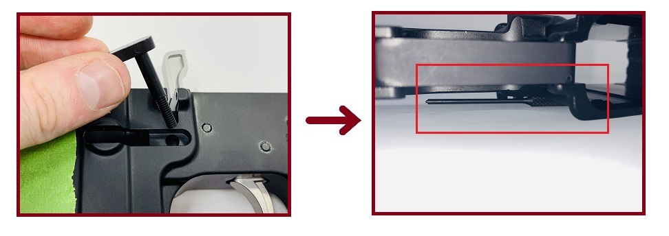
10. Install the Safety Selector Lever and Pistol Grip
- Parts: Safety Selector Lever, Safety Detent, Detent Spring, Pistol Grip, Hex Bolt, Washer.
- Tools: 3/16" Allen Key or Allen Head Socket.
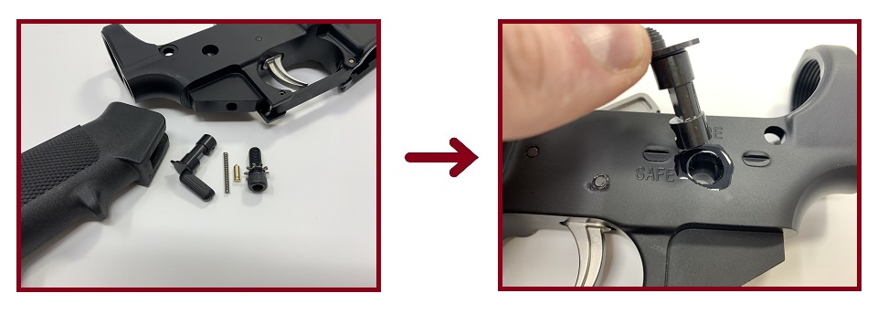
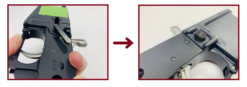
The safety selector lever and pistol grip must be installed together, as the grip helps to retain the safety lever's spring and detent. Collect all hardware listed and lubricate the safety pin hole. Then, insert the safety lever through the hole. There will be some resistance; Gently wiggle the lever to assist with seating it.
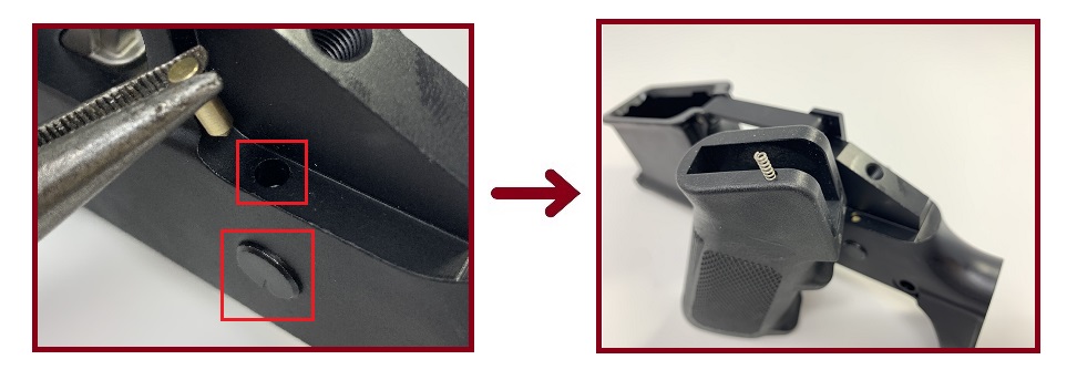
Once fully seated, the safety lever should just protrude outside the opposite side of the receiver, shown in the larger red square above. Next, flip the receiver upside down and insert the safety lever detent into the detent hole shown in the smaller red square above. Insert the safety lever detent spring into the small hole drilled atop the pistol grip.
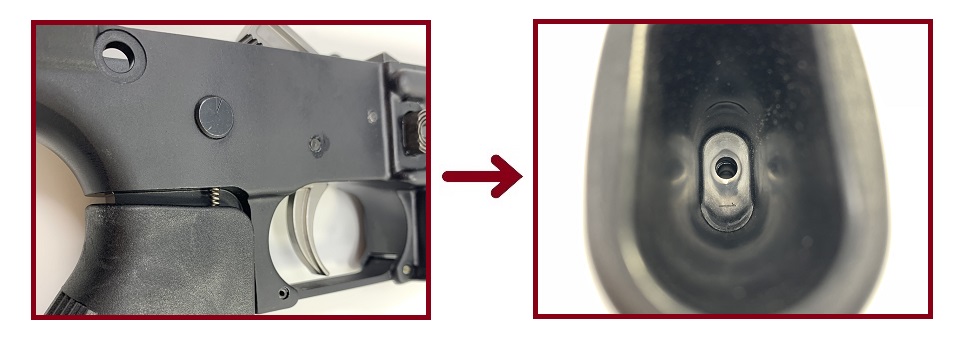
Install the pistol grip onto its mount, ensuring the detent spring aligns with the safety lever detent. Ensure the receiver's pistol grip bolt hole is aligned with the hole inside the grip.
With the bolt hole and grip hole aligned, insert the hex-head bolt and washer. Use a 3/16" Allen key or Allen-head socket to tighten. If using a torque wrench, tighten to 55 in.-lbs. If not using a torque wrench, simply tighten until hand-tight, then give the bolt one extra half-turn. Remember, you're threading steel into aluminum. The receiver floor can crack with excess torque. The supplied washer will provide a sufficient mechanical lock with basic hand-tightening.
11. Install the Rear Takedown Pin
- Parts: Rear Takedown Pin, Takedown Pin Detent.
- Tools: None.
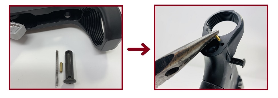
Collect the rear takedown pin and takedown detent (the pictured detent spring will be used in the next step). Lubricate the takedown pin and insert it into the pin hole in the right side of the receiver. View the back of the receiver and insert the takedown pin detent into the small hole located next to the latch plate mount, below the buffer tube housing.
12. Install the Buffer Tube and Buffer Retainer
- Parts: Takedown Detent Spring, Buffer Tube, Castle Nut, Latch Plate, Buffer Retainer, Retainer Spring.
- Tools: Castle Wrench / Armorer's Tool, 5/32" Punch (Optional).
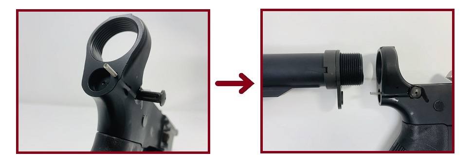
Insert the rear takedown detent spring atop the detent in the same hole as the previous step. Collect the buffer tube and install the castle nut onto the threads. Thread the nut to the end of the threads and ensure the "crown" of the castle nut is facing the rear of the tube. Slide the latch plate onto the threads behind the castle nut.
Thread the buffer tube into the housing until the latch plate just touches the rear takedown detent spring. Collect the buffer retainer and retainer spring. Insert the retainer spring into the hole inside the buffer tube housing's threads.
Insert the buffer retainer atop the spring and compress it with the 5/32" punch. You could do so by hand, but the spring tension is high and this may cause discomfort. With the buffer retainer compressed, continue threading the buffer tube into place until it meets the buffer retainer. The lip of the buffer tube should rest on the retainer itself, next to the nipple protruding from the middle of the retainer. This nipple keeps the buffer and buffer spring seated once your rifle or pistol is assembled.
NOTE: While threading the buffer tube to meet the buffer retainer, the rear takedown detent spring may bend or fall out. This is not a concern; Simply place the spring back into the hole once the tube is appropriately threaded. If the spring is slightly bent, this is okay. We'll address this in the next step.
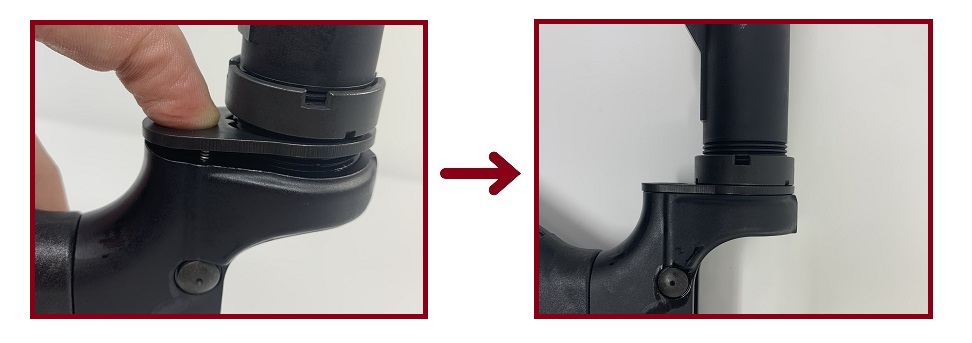
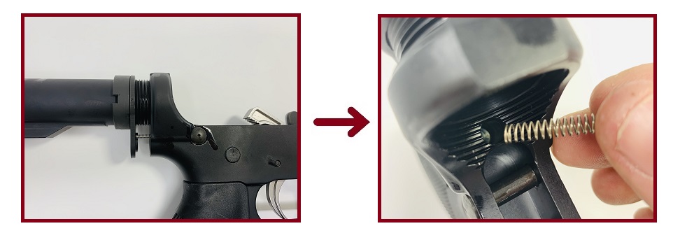
Ensure the rear takedown detent spring is resting in its hole. Gently compress the spring by pressing the latch down atop it. Press down on the plate until it is flush with the backside of the buffer tube housing. Then thread the castle nut up against the latch plate until it, too, is flush.

Remove the buttstock or brace from the buffer tube or pistol tube (if necessary) by pulling on the adjustment lever to unseat the locking pin inside the brace/stock from the tube. Slide your Castle Nut Wrench or Armorer's Tool over the castle nut, ensuring the teeth on the wrench line up with the crown. Tighten the castle nut.
NOTE: The same discipline applies here as with the pistol grip bolt: Hand-tight with a quarter- to half-turn extra is sufficient for keeping the tube in place. For additional security, the castle nut and threads can be staked in similar fashion to the hex bolts on a bolt carrier group, though this is rarely necessary.
With the castle nut tightened and your buttstock/brace reinstalled...
Your Lower Parts Kit Install is Complete!
Your finished AR-15 lower receiver is now assembled and ready to accept a buffer, buffer spring, and complete upper receiver. If you're running into trouble with the trigger or fire control group after the install, don't fret too much. Here are some of the common problems that affect new LPKs, and how to fix 'em.
Troubleshooting Trigger Reset Failure
To troubleshoot functionality issues, check to make sure that your lower receiver and LPK aren't suffering from one of these issues:
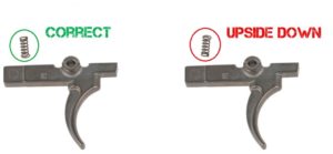
1. Hammer and Trigger Spring Orientation
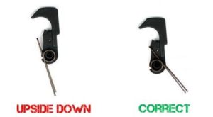
The hammer and trigger springs are directional. If they're installed upside down, they won't allow the hammer or trigger to work properly.
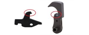
2. Disconnector Spring Orientation
The disconnector spring is shaped like a cone. The larger base of the spring should be seated atop the trigger, while the skinny end should fit into the notch on the bottom of the disconnector. Check to make sure it's not installed upside down.
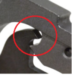
3. Polish the Hook and Disconnector
The hammer's hook and disconnector rely on very tight tolerances to work together correctly. Sometimes, new LPKs can have extra bits of metal, rough edges, or small burs that create extra friction on these contact surfaces. This can prevent the trigger from resetting. Check to ensure the hook and disconnector separate cleanly without binding or resisting. Do this by test-firing the lower receiver while empty, with the receiver opened up so you can inspect both units.
Warning: Be very careful when polishing or de-burring the hook and disconnector. Removing too much metal or rounding off the edges on the hook or disconnector can potentially kill your trigger assembly's function. We recommend test-firing a few rounds to work out the issue, first. Sometimes, firing a few rounds and "breaking in" the trigger group is enough to fix the problem.
If you still need to polish the surfaces to get the trigger working, we strongly recommend using very fine-grit sandpaper or steel wool (at least 1,000-grit or higher). Make a few light passes, then test-fire again until the problem goes away. The notch in the bottom of the hammer where the trigger's sear connects may also be a point to polish. This can improve trigger feel and reduce creep and take-up.
4. Check Hook and Disconnector Tolerance
Sometimes, the tolerance between the hook and disconnector might simply be out-of-spec. The distance between the hammer and the hook (with the trigger at rest and the sear holding the hammer) should be 0.003". With the trigger depressed, press the hammer down to check if the hook is captured by the disconnector. If it misses, your tolerance is too great.
5. De-burr the Hammer and Trigger Pins
The hammer and trigger pins can feel gritty, too. They need to be smooth so the hammer, trigger, and disconnector can rotate freely. Check for burs by opening up the receiver, cocking the hammer, and pulling the trigger. Hold down on the hammer with your thumb while doing this. Allow the hammer to slowly rise up with your thumb. If you feel binding or resistance, the pins are likely in need of some light polishing.
You can work these burs out by simply working the trigger, disconnector, and hammer repeatedly. Apply oil to the fire control group while doing this. If you still feel resistance after working the assembly, you may need to remove the pins and lightly polish them.
DISCLAIMER: If you are new to the world of DIY gun building, you likely have a lot of questions and rightfully so. It’s an area that has a lot of questions that, without the correct answers, could have some serious implications. At GunBuilders.com, we are by no means providing this content on our website to serve as legal advice or legal counsel. We encourage each and every builder to perform their own research around their respective State laws as well as educating themselves on the Federal laws. When performing your own research, please be sure that you are getting your information from a reliable source.